Steam Safety or Hot Water Relief Valve Installation Requirements
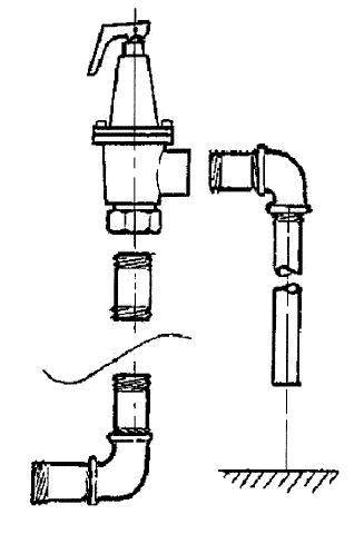
Safety or relief valves shall be installed at the top of the boiler with the spindle of the valve in an upright vertical position. The inlet and discharge piping shall be as short and direct as possible. Safety and relief valve set pressure and capacity are determined by data from the manufacturer’s nameplate or stamping on the boiler.
Direction of Valve
Safety or relief valves shall be installed in an upright vertical position
Inlet Piping
Safety and relief valve inlet and inlet piping shall be equal in diameter
Safety and relieve valve inlet and inlet piping diameters shall be equal or smaller than the opening or port to which it is attached on the boiler
Discharge Piping
Discharge piping shall not restrict the flow from the safety or relief valve
Discharge piping diameter shall be the same size or larger than the discharge opening of the safety or relief valve
Distance from floor or air gap no greater than 6 inches
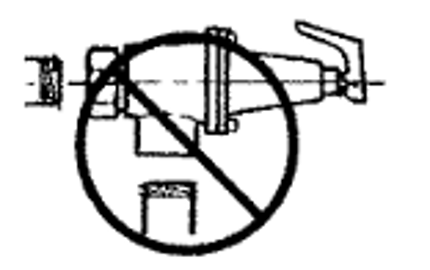
Incorrect Installation
Safety or relief valves shall not be piped in the horizontal position as shown below
Safety Labeling
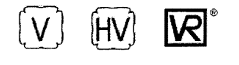
Steam safety and hot water relief valves that are installed on boilers shall be identified with the ASME “V”, “HV”, or National Board “VR” Symbol.