0.5 Chlorine Residual Disinfection for Health Care Facilities
Background
Potable hot water in a hospital, community−based residential facility, inpatient hospice or nursing home shall include a method or device for disinfection of the hot water distribution system. The storing and circulation of hot water shall be either initiated at a minimum of 140°F with a return of a minimum of 124°F, chlorinated at 2 mg/L residual, or disinfected by another system approved by the department.
Goals of Rules and Policies
The goal of this guidance document is to protect public health of inpatients within a health care facility by disinfection of the hot water supply system.
Applicable Rules
Wisconsin Administrative Code:
Alternate Product Approval File No:
20110370
Applicable Policy on Alternate
The use of free chlorine is “another disinfection system” approved by the department for compliance to SPS 382.50(3)(b)6.c. The installation of a water treatment device requires department plan review under SPS 382.20. The following procedures and documentation must be followed and maintained.
Procedures
The maximum residual disinfection level goals (MRDLGs) as per SPS 382.22, NR809.561, NR809.80:
The maximum residual disinfectant concentration may not exceed 4.0 mg/L.
The minimum residual disinfectant concentration must be at least 0.5 mg/L.
The system shall be designed and installed to achieve the minimum inactivation rate (“CT” value).
The maximum contaminant level of byproducts must not exceed 0.080 Trihalomethanes (TTHM) and 0.60 Haloacetic Acids (HAA5).
Each potable water system using chlorine disinfection shall be automatically and continuously disinfected by means of disinfectant and feeding equipment.
Disinfectant and filter aid feeding shall be conducted as follows:
Liquid chemicals shall be fed into water circulation piping by means of a positive displacement feeder either at full strength or diluted with potable water.
If a chemical that forms a residue is used, a two tank system shall be used. One tank shall be used for mixing the solution and settling the precipitate. The clear liquid shall be decanted or siphoned into the second tank for distribution.
Feeders shall comply with the following:
All disinfectant feeders shall be installed according to the manufacturer’s directions and used only with the disinfectant recommended by the manufacturer.
Feeders shall be automatic, easily adjustable, capable of providing the required chemical residuals, equipped with flow control valves upstream and downstream from the feeder, easily disassembled for cleaning and maintenance, durable, and capable of accurate feeding.
Feeders shall be properly vented and incorporate anti-siphon safeguards to prevent disinfectant feeding in the event of the failure of recirculation equipment.
Feeder pumps shall be electrically connected to the recirculation pump control circuit and have a separate disconnect switch.
Feeders systems (pump, tanks, piping/tubing materials) shall be suitable for use in a potable water supply and shall be third party certified or approved by the department.
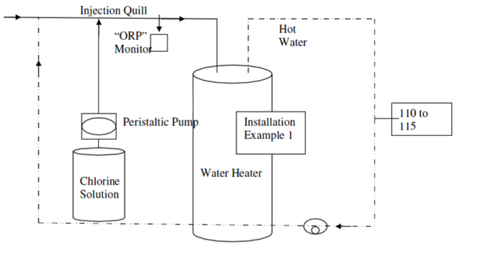
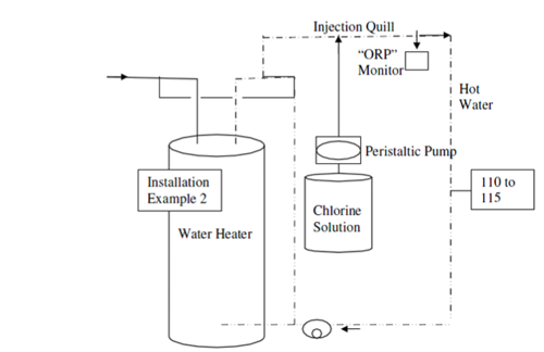
Feeder systems shall be located to disinfect the entire hot water system per SPS 382.50.
Disinfectant shall comply with the following:
The disinfectant must comply with NSF/ANSI 60 International Standard for Drinking Water Additives.
The disinfectant has an effective residual that can be measured easily and accurately by an approved field test procedure.
The disinfectant is compatible for use with other chemicals normally used in the water treatment or is clearly identified as having a use limitation.
The disinfectant does not impart toxic properties to the water when used according to the manufacturer’s directions.
The disinfectant does not create an undue safety hazard when handled, stored or used according to the manufacturer’s directions.
All chemicals used in the operation, and bulk storage tanks containing the chemicals shall be conspicuously labeled with the following information:
Name of the product
The manufacturer’s name and address
Active ingredients
Directions for use
Hazardous ingredient warning
The U.S. environmental protection agency registration number
Water Testing
As per SPS 382.22 and NR809.565, a daily sample shall be taken at the nearest and the furthest point of hot water use from the injection location and tested for free chlorine residual.
A potable water disinfection system that has a properly functioning electronic monitoring device installed to control disinfectant residual shall be:
Manually tested at least once a day for disinfectant residual and pH with an approved test kit, or
Managed by a continuous monitoring system in compliance with a water management plan approved by the department.
Quarterly testing for disinfection by-products (DBP) shall be performed.
A test kit of a type approved by the department shall be maintained for testing the water pH; the disinfectant residual; and DBP.
Water samples should be taken during the day for accurate disinfection levels. A record shall be kept of the daily water quality test data. The data shall include:
Location of sample
Date and time sample taken
Sample result
Identification of person taking sample.
An accessible hose bib shall be located in the area of the chlorine system.
Chlorine systems should be maintained and serviced by qualified individuals.
Special Considerations
An oxidant demand study should be completed to determine an approximate chlorine dosage to obtain the required CT value as a disinfectant. Water system owners are encouraged to routinely monitor the effectiveness of the water treatment system.
Documentation
A record shall be kept on dates of cleaning, replacement of components or parts, and when the device was shutdown and the reason for shutdown.
Department and Health representatives shall be provided access to the water treatment system and records upon request.
Notification
The Department of Health Services is to be cc’d as part of this approval. Email to DHSDQAPlanReview@dhs.wisconsin.gov
Department Tracking
The Division of Industry Services reserves the right to amend/revise this document as conditions arise making them necessary for code compliance and/or to protect public health and the waters of the state. For more information contact a Wisconsin Department of Safety and Professional Services Plumbing Consultant at DSPSSBPlbgTech@wisconsin.gov
Example Systems