Interior Grease Interceptor Venting Requirements
Is a vent always required by code to serve the drain line immediately downstream of an interior grease interceptor?
No.
The Wisconsin plumbing code does not require a vent on all installations of interior grease interceptors. Over the years, manufacturers have updated their installation requirements as well as the technologies used when developing interceptors. Some interceptor literature states: “vent not required unless by local code.” The practical installation of an interceptor does not always prohibit the free circulation of air in the drain piping immediately downstream, it is simply a pass-through collecting fat, oils, and/or grease and does not create a code-defined trap thus, no vent is required. When the circumstance arises where there is not a free circulation of air in the drain piping immediately downstream of a grease interceptor, DSPS code would require a vent, but only when the air flow is prohibited. If air flow is not prohibited, the code does not require a vent downstream of an interceptor.
For years, the industry standard was to label these as a “grease trap” but that is no longer the case. The term “grease trap” is not present in DSPS code nor in any of the Department’s adopted standards. By definition, a grease interceptor is an appurtenance, and not a plumbing fixture. The only vent required by code related to an interior grease interceptor is when an orifice-type flow control is installed.
A key factor when deciding if a vent is required is the flow control mechanism. Newer technologies and applications have provided for other options than just orifice-type flow controls. Some models are equipped with flow control that happens inside the interceptor itself. There is a cartridge inside the inlet dip tube providing free air circulation not only for the interceptor but also for the associated piping both upstream and downstream.
Where required by the manufacturer, typical orifice-type flow controls are installed in the piping upstream of the interceptor, as per Wisconsin Administrative Code Section SPS 382.34(5)(d)4.b., and use an orifice smaller than the piping in which it is installed. The throttling of the waste through the orifice-type flow control is the cause for requiring extra air inlets and vents. The adopted standard ASME A112.14.3 does not mandate the use of external vented flow control and air injection. This can be accomplished with internal flow control devices that are not orifice-type.
Wisconsin Plumbing Code References
SPS 381.01(10) “Appurtenance” means a manufactured device or prefabricated assembly of component parts which is an adjunct to a plumbing product or plumbing system.
SPS 381.01(113) “Grease interceptor” means a receptacle designed to intercept and retain or remove grease or fatty substances.
SPS 381.01(136) “Interceptor” or “separator” means a device designed and installed so as to separate and retain deleterious, hazardous or undesirable matter from wastes flowing through it.
SPS 381.01(259) “Trap” means a fitting, device or arrangement of piping so designed and constructed as to provide, when properly vented, a liquid seal which prevents emission of sewer gases without materially affecting the flow of wastewater through it.
SPS 382.31(3) GENERAL. (a) Vents. Every trap and trapped plumbing fixture shall be provided with an individual vent, except as otherwise permitted in this chapter.
SPS 382.34(5)(d)4. ‘Flow controls.’ Where required by the manufacturer, devices which control the rate of flow through an interior grease intercept shall be installed.
SPS 382.34(5)(d)4. b. Flow controls shall be installed in the drain branch leading to each fixture and shall be so rated that the combined flow from all combinations of discharge will not develop either sufficient static or velocity head so the established flow rate of the interceptor can be exceeded.
SPS 382.34(5)(d)5. ‘Flow control vents.’ Orifice type flow controls for an interior grease interceptor shall be vented in accordance with s. SPS 382.31.
Wisconsin Statutory References
Chapter Section 145.01(10)(a)5. “Plumbing” means: A plumbing and drainage system so designed and vent piping so installed as to keep the air within the system in free circulation and movement; to prevent with a margin of safety unequal air pressures of such force as might blow, siphon or affect trap seals, or retard the discharge from plumbing fixtures, or permit sewer air to escape into the building; to prohibit cross−connection, contamination or pollution of the water supply and distribution systems; and to provide an adequate supply of water to properly serve, cleanse and operate all fixtures, equipment, appurtenances and appliances served by the plumbing system.
Example Interior Grease Interceptors
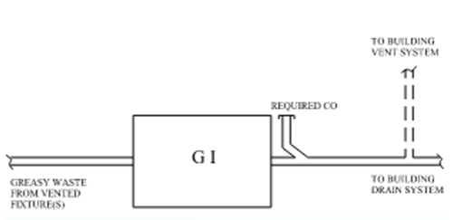
Examples A through H show the different configurations for when a vent is required. ‘GI’ is the acronym for grease interceptor.
Example A
No vent required by manufacturer. No flow control required by manufacturer. Free circulation of air immediately downstream of grease interceptor.
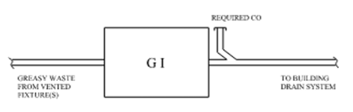
Example B
Vent required by manufacturer. No flow control required by manufacturer. Free circulation of air immediately downstream of grease interceptor.
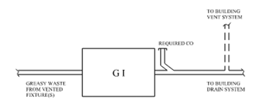 Example C
Vent required by manufacturer. Flow control required by manufacturer. Free circulation of air immediately downstream of grease interceptor.
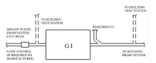 Example D
Vent required by manufacturer. Flow control required by manufacturer. No free circulation of air immediately downstream of grease interceptor.
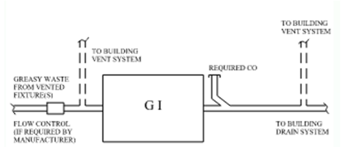
Example E
No vent required by manufacturer. Flow control required by manufacturer. No free circulation of air immediately downstream of grease interceptor.
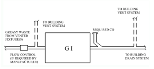
Example F
No vent required by manufacturer. No flow control required by manufacturer. No free circulation of air immediately downstream of grease interceptor.
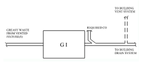
Example G
No vent required by manufacturer. Flow control required by manufacturer. Free circulation of air immediately downstream of grease interceptor.
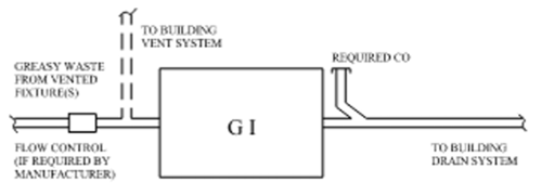
Example H
Vent required by manufacturer. No flow control required by manufacturer. No free circulation of air immediately downstream of grease interceptor.