
Pure Water Systems
Background
“Pure water” is the term generally used to describe water that is free from particulate matters, minerals (soluble ions), bacteria, pyrogens (any substance or agent that tends to cause a rise in body temperature, such as some bacterial toxins.), organic matters, and dissolved gases, which frequently exist in the potable water supply. Pure water systems are usually required in the hospital’s pharmacy, central-supply room, laboratories, and laboratory-glassware washing facilities.
There are two basic type of pure water available in hospital facilities: bio-pure water (water containing no bugs or other life forms) and high-purity water (pure water that is free from minerals, dissolved gases, and most particulate matters).
Water purity is most easily measured as specific resistance (in ohm-centimeter units) or expressed as parts per million (ppm) of an ionized salt. The theoretical maximum specific resistance or pure water is given as 18.3MΩ-cm at 770F (250C). This water purity is difficult to produce, store, and distribute. This water is “starved” for impurities and constantly attempts to absorb contaminants. It is important to note that the specific resistance of the pure water is indicative only of its mineral contents and in no way shows the level of bacterial, pyrogenic, or organic contamination. An independent laboratory analysis should be made, whenever possible.
Goals of Rules and Policies
The goal of this guidance document is to protect public health of inpatients within a health care facility by producing pure water through processes of distillation, demineralization, reverse osmosis, filtration, and/or recirculation of the water supply system.
Applicable Rules
Wisconsin Administrative Code
Methods
The five basic methods of producing pure water are as follows: distillation, demineralization, reverse osmosis, filtration, and recirculation. Depending upon the type of pure water required in the facility, one (or more) of these methods will be needed. Under certain conditions, a combination of several methods may be necessary.
Distillation
Produces bio-pure water, which is completely free from particulate matters, minerals, organics, bacteria, pyrogens, and most of dissolved gases.
Distilled water a minimum specific resistance of 300,000 Ω.
An important consideration in this case is that the water is free from bacteria and pyrogen contamination, which is dangerous to the patients, particularly where intravenous solutions are concerned.
Demineralization
Sometimes called “deionization” produces high-purity water that is completely free from minerals, most particulate matters, and dissolved gases.
Depending upon equipment used, it can have a specific resistance ranging from 50,000 Ω to nearly 18 MΩ.
It could be contaminated with bacteria, pyrogens, and organics (these contaminants may be produced inside the demineralizer itself).
Demineralized water can be employed in most laboratories, the laboratory’s glass-washing facilities (as a final rinse) and as a pre-treatment for still feedwater. The typical demineralizer apparatus consists of either a two bed deionizing unit or a mixed-bed deionizing unit.
Reverse Osmosis
Produces high-purity water that does not have the high resistivity of demineralized water and is not bio-pure.
An RO process can be used as pretreatment for demineralization.
Note: Chlorine must be removed from the water, otherwise it will destroy the RO membrane.
Filtration
Various types of filtration are currently available to remove particulate matters from water as pre-treatment (Ultra-filtration, Nano-filtration, etc.).
Recirculation
High-purity systems should be provided with a circulation loop.
Dead-end legs should be avoided whenever possible or limited to 50 inches.
System design velocity should be between 4 and 7 ft/s so as to discourage bacteria accumulation and provide transport back to the ultraviolet sterilizer and filtration for removal.
Materials
General pure-water component requirements include:
Inert materials
must not leach contamination into the water
Clean joining methods
avoid solvents, lubricants, and crevices
No material erosion
must not flake off particles
Material should not enhance microorganism growth
Material should be smooth, crack and crevice-free, and nonporous
Common pure-water component materials include:
tin lined
stainless steel
glass or glass-lined
polypropylene
PVC
PVDF
Common pure-water piping materials-Approved Wisconsin
Polyethylene (PE) NSF 51; NSF 61
Polypropylene (PP) NSF 51; NSF 61
Polyvinylidene fluoride (PVDF) NFF 51; NSF 61
Polyvinyl chloride (PVC) NSF 51; NSF 61
Installations and Conditions
The connection of the potable water supply to the high-purity water system is required to have cross-connection protection.
Dead-end legs need to be less than 50 inches.
Provisions for future cleaning and disinfection.
Tank vent filtration to prevent microbial contaminants from entering water storage
Pure water systems are to be identified per Table 382.40-1a as device specific water and labeled for the specific use.
Pure water systems are to designed and maintained to achieve the quality intended.
If a serrated nipple is installed on the pure-water faucet, the faucet is to be labeled with signage as to the specific use of the faucet (water) and include verbiage: “If a hose is connected to the faucet, it is to be removed immediately after each use.”
Equipment connected to the pure-water system is to have product approval.
A cross-connection control device protecting the pure water system shall conform to ASME A112.18.3., NSF 51 and NSF 61.
Normal Wisconsin approved backflow protection that incorporates “air vents” have the potential to be contaminated from air-borne microorganisms.
Documentation
The owner of the facility is responsible for quality of the pure water system.
A record shall be kept on dates of cleaning, replacement of components or parts, and when the device was shutdown and the reason for shutdown.
Department and Health representatives shall have access to the water treatment system and records on request.
Notification
The Department of Health Services is to be cc’d as part of this approval. Email to DHSDQAPlanReview@dhs.wisconsin.gov
Department Tracking
The Division of Industry Services reserves the right to amend/revise this document as conditions arise making them necessary for code compliance and/or to protect public health and the waters of the state. For more information contact a Wisconsin Department of Safety and Professional Services Plumbing Consultant at DSPSSBPlbgTech@wisconsin.gov
Example Systems
Bio-Pure and High-Purity Water Component/Piping Layout
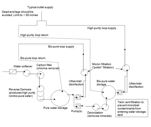 The system starts with a water softener depicted by a square with a dash through it and a circle that feeds into a carbon filter (chlorine removal) that is depicted by a circle.
Below that are three ovals stacked on top each other which depict reverse osmosis (produces high purity non bio-pure water)
This feeds into the pure water storage which is depicted as a large circle. It feeds into pumps which are depicted by small squares with small circles inside of them. The pumps feed into two sections.
On the left of the pump feed is ultraviolet disinfection and micron filtration (polish filtration) depicted by a circle and that feeds into a line labeled bio-pure loop supply. Halfway through this line becomes dotted and is labeled bio-pure loop return. This feeds back into the pure water storage.
On the right of the pump feed is deionization (removes minerals) which is depicted by two circles that feed into each other and then feeds out to bio-pure water storage.
The bio-pure water storage feeds into a pump into ultraviolet disinfection and up into micron filtration (polish filtration). This feeds up into high-purity loop supply and that opens upward to typical outlet supply (dead-end legs should be avoided. Limit to less than 50 inches) and the high purity loop supply continues downward as a dotted line labeled as high purity loop return that feeds back into the bio-pure water supply.
Note: Tank vent filtration to prevent microbial contaminants from entering water storage tank.
High-Purity Water Component/Piping Layout
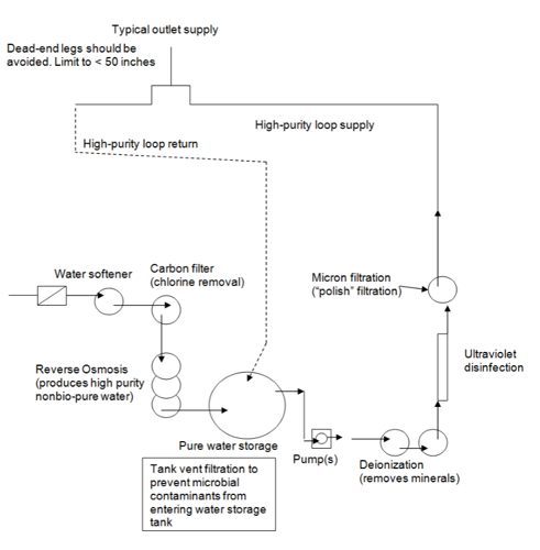 The system starts with a water softener depicted by a square with a dash through it and a circle that feeds into a carbon filter (chlorine removal) that is depicted by a circle.
Below that are three ovals stacked on top each other which depict reverse osmosis (produces high purity non bio-pure water)
This feeds into the pure water storage which is depicted as a large circle. It feeds into pumps which are depicted by small squares with small circles inside of them.
The pumps feed into ultraviolet disinfection and micron filtration (polish filtration) depicted by a circle and that feeds into a line labeled high purity loop supply. This opens upward to typical outlet supply (dead-end legs should be avoided. Limit to less than 50 inches). Halfway through this line becomes dotted and is labeled high purity loop return. This feeds back into the pure water storage.
Note: Tank vent filtration to prevent microbial contaminants from entering water storage tank.